Tumult and Disaster
Spinner
Probably one might believe in Carl Tilley´s statement, "the system does not use back EMF, scalars, magnets, pulses in any form, waves or custom waveforms, no resonance, no frequency beyond the revolutions of the DC-motor, no high voltage electrostatics." So merely everything is excluded - besides e.g. electrostatics at the range of relative low voltage? Probably one might believe also in Carl Tilley´s remark, the logo of his company would represent the principles of his invention. As I remember (his original website is no longer available) that emblem did look like the graph at picture 09.12.01 right side: three V-shaped elements embedded within each other (here marked by different colours). Based on these statements, I try to find a solution for these problems at the following.
Cone
Like at machines of previous chapters, the rotor mainly exists by non-conductive material. At the other hand must exist faces of conductive material, which are charged when starting the system. Here, the rotor-charge-face is signed C1. At most simple case, that green area covers some less than half of the side-face.
At the middle row at D and E additional cone-shaped shells are drawn around the rotor-cone (grey). This stator (ST) exists also by non-conductive material (blue) excepting a section of conductive material (yellow). Also this face C2 is charged when starting the system. Below at F, once more the side-face of the rotor is drawn with its charge-face C1. Opposite of, the stationary charge-face C2 is positioned. This is some smaller, so the rotating charge-face C1 temporary covers the stationary charge-face C2 completely.
Right side at this picture at G and H one more cone-shaped shell is drawn around previous constructional elements. Also this intermediate storage (ZS) exists by not-conductive material (light-red) excepting a section of conductive material (dark-red). Also that face C3 is charged when stating the system. All three faces (C1, C2 and C3) store electric charge and are (nearby) of likely size. At this picture below right at H, two discs (pink) are fix mounted at the shaft (dark-grey), which are used for mechanical control (MS) of the system.
Charge-Shifting
At B the rotor-charge-face did turn so far, it begins to cover the stator-charge-face. Corresponding to the rotor, also the upside disc of the mechanical control (MS, pink) did turn some forward. Now a slide-contact (K23, pink) builds a conductive connection between C2 and C3, so the charge displaced from the stator can flow on the charge-face of the intermediate storage.
At C the rotor-face (green) covers the stator-face (yellow) completely. The slide-contact now is positioned outside of the stationary faces, so the connection between C2 and C3 exists no longer. The stator-face is ´pressed empty´ and finally shows few charge, e.g. corresponding to only 6 V. Accordingly at the intermediate storage, the density of charge did rise up to 18 V.
About one half revolution the charges keep separated, until the rotor-face completely did move off the area of the stator-face, like sketched at D. Also the below disc of mechanical control is turning with the rotor. At this situation, a slide-contact (K321, light-blue) builds a conductive connection between all three faces for a short moment. The previous separated charges become balanced, i.e. all show 12 V again, so the process can repeat.
Differing Charge-Layers
At B the rotor did turn by 180 degree, so now its charge-face covers the stator-face. Their charge-layer (C2, yellow) now is compressed and represents e.g. only 6 V. At upper part with the increased voltage, the rotor-charge affects even stronger pressure respective the charges are faster ´swirling´. The voltage of intermediate storage (C3) thus corresponds not only to previous 18 V, but 3 V stronger, thus showing 21 V.
Right side at C the rotor did go on turning and via slide-contact K321 the charges of all three faces are balanced - now each showing voltage of 13 V (versus the earth). So it´s well possible, that system increases the intensity of charge-swinging by itself, thus rising up the voltage. The normal swinging of charge becomes ´turned-up´ by the stroke-component of the aether, resulting from the continuous turning rotor (see previous chapters for details).
Changing Charge-Pressure
Right side at B, the rotor-charge-face did move two sections towards left. The charges there mutually compress each other to a level of each 6 V. At the rotor the ´excess´ parts of charge got spread to the remaining two sections, which now show stronger voltage of each 18 V. At the stationary faces, the ´pushed-off´ charges got spread on remaining six sections, thus each now showing voltage of 14 V. If the rotor-face goes on moving left, its 18 V are working against the 14 V of next stationary section.
Right side below at C now three sections mutually cover. From the original 4*12 V = 48 V of the rotor-face now exist 3*6 V at the left three sections and at the remaining right section the voltage rised up to 30 V. At the stationary faces the displaced parts of charge can spread onto more sections, which now show voltages of each 15 V to 16 V. That 16-V-voltage of left stator-section thus is opposed by the 30-V-voltage of the right rotor-section.
Below left at picture 09.12.05 at D, the rotor- and stator-sections cover completely - and ´stress´ comes up within the aether between C1 and C2. At the rotor-face the charge will spread again equal (with 12 V at each section). Probably the charge at stator-sections were compressed below that level of 6 V. So at the intermediate storage C3 will exist a charge-layer of at least 18 V. In order to avoid previous stress, the rotor-face should be some wider than the stator-face. The ´surplus´ voltage of the rotor will concentrate at the edges and thus will push-off the charge from the stator at its best.
The charge at stator-face thus becomes shifted to the face of the intermediate storage at least by half, so a voltage-difference of 18 - 6 = 12 V is achieved. This gradient results a current-impulse when both stationary faces are connected (at next phase, e.g. by previous slide-contact K321). This difference corresponds to the strength of the rotor-charge, which finally is unchanged. It´s only temporary used to compress the charge-layer of the stator down to 6 V and same time to pile up the charge-layer of the intermediate storage by 6 V to the level of 18 V. The shifting of charges is possible, because the rotor-charge can not ´escape´, the stator-charge however can spread onto wider surface.
Charge-Storage and Flow
The intermediate storage must not be a V-shaped cone-shell. Here for example, the intermediate storage (ZS respective C3, red) is drawn as a ring upside of rotor- and stator-cone. The disc of the mechanical control (light-grey) is turning with the shaft and the rotor. During the phase when charge is pushed off the stator-faces, the contact K23 builds a conductive connection, where the displaced charge-parts are pressed into the intermediate storage.
As soon as the rotor-faces did move off the stator-faces, below at the short radius a conductive connection between C3 and C2 starts. The voltage-difference results a current-impulse (within the light-red conductor-wires), usable by a consumer (V, light-blue). Short moment later, a contact to C1 could allow the balancing of voltages of all three faces. Here these contacts are simplistic drawn as K321 (light-blue). At any case that back-feeding should be done at the narrow end of the cones, because at the wide end the charges are stronger whirled up.
The upside mentioned statement of Carl Tilley excluded many elements - however not the usage of coils. Probably the green ring at his logo (picture 09.12.01 right side) could be interpreted as a coil. This picture here below at C shows a coil, which is bi-filar winded - usable as an alternative intermediate storage. Such coils can take great charge-volumes with few resistance. The general aether-pressure can push off the charge by an current-impulse likely effective. A V-shaped intermediate storage is hard to build, so as an alternative could be used a bifilar-coil or a massive ring, a sphere or a capacitor with variable capacity (capacitors, coils, induction etc. are discussed at later chapters in details).
Constructional Elements
A motor (MO, light-blue) must drive the rotor. The motor could be build wider than necessary respective additional mass could serve as a ´flywheel´, in order to build up an intensive aether-aura. Also permanent magnets could be embedded, just for increasing the vortices of the aura. Generally, the magnetic fields of the motor should be aligned parallel to the axis. Thus a ´stroke-component´ comes up at the surrounding aura, which indirectly increases the swinging motions of the charge.
As the rotor is turning, charge-layers of different heights come up, thus voltage is piled up corresponding to the turning-speed. Afterward the voltage-difference becomes balanced, because the general aether-pressure - by speed of light - levels down the oversize charge-layer and thus pushes a current-impulse along the conductor-wires. At this picture the general ways (light-red) for flows of current schematic are drawn. Some more constructional elements (light-blue) are included, e.g. consumer (V) and batteries (BA) and a control-unit with diverse functions. The elements used at Carl Tilley´s system are listed and described in details at the web, e.g. by Jerry Decker at KeelyNet. At the following only verbal descriptions of the demanded functions may give an overview.
Controlling Functions
Upside was described a mechanical control via slide-contacts. Naturally these functions could be done also by electronic control-units. As mentioned upside, the system even could build up high charge and voltage autonomously. So at any case a switch must be available to allow the rotor-charge flowing-off into the ground (B). It might be advantageous to control the rotor-charge by a separated rotor-management (ROM). All sections of the rotor-charge-faces should be connected by a ring at the narrow end of cone - and there probably a slide-contact will be necessary. The fed strength of charge at the rotor-faces determines the maximum achieved voltage between stator and intermediate storage. Instead of previous example of 12 V, one could work with 72 V or 144 V or even stronger voltages.
The charge of the rotor-face should be some stronger than the charge at the stator-face. The stator-charge determines the maximum displacement of charge-volume, thus determines the strength of the current. Charge may not be pressed ´backward´ at the faces and wires, not at the rotor and not at the stator. So suitable elements at all sketched current-ways must guarantee the wanted current-directions. In addition, the stator-management (STM) must open the back-flow (C) of the charge at the right moment. When testing the system or driving the system with variable charge-strength, the air-gap between rotor and stator should be variable, e.g. by axial shift of the stator.
The management of the intermediate storage (ZSM) has different functions. The connection between stator and intermediate storage (ways D and E) must guarantee the charge-flow only into that direction. Thus a rectifier there must hinder a ´back-slosh´. At the other hand, the flowing-off (F) from the intermediate storage must occur just at the right moment: when the rotor-charge-faces passed the stator-charge-faces, because only at that moment the stator-faces can take new charge. That current-impulse e.g. could run through the primary-coil of a transformer, thus via way C most direct back into the stator. Afterward, the ways C and F must be interrupted immediately, so the charge within the intermediate storage can be piled up again.
That intermediate-storage-management (ZSM) generally must transform the arriving current-impulses (F) into suitable shape as demanded for the power-supply of all other components of the control unit. If the external consumers need different frequencies, voltages, strengths or temporary varying demands, a separate unit of consumer-management (VM) could prepare the current in suitable shape.
Construction
The pictures available at the web, at the one hand show that small spinner - and all around Carl Tilley obviously arranged a rather chaotic assembly of electronic elements. Many electro- and electronic-crafts have sufficient knowledge to understand and rebuild such a system. Now I really hope, many hobby-handicrafts want to convince themselves, that stuff is really working. Naturally that alternative solution might be very important for professional producer of electric generators. However this demands mental latitude to believe the possibility of COP > 1 - what´s actually the unique sense for all efforts.
Remember: any heat-pump is a surplus-machine - where the environment-heat delivers performance for free. Any wing of planes is a surplus-machine, demanding few input for drive to produce a pressure-difference within the air - and the general atmospheric pressure delivers much stronger lift-force for free. Here that shifting of charge generates a sink and source in shape of voltage-potential - and the general aether-pressure delivers current-impulses, usable e.g. by electromagnetic processes with surplus-benefit for free.
Nashville, Tennessee, USA, 2002: a certain Carl Tilley caused excitement with the claims to drive his workshop without external power supply, to drive cars with electric units and same time charge the batteries. He announced to drive ships and airplanes to approve that autonomous power-supply. His invention thus would solve every energy-problem and he would sell it for ´only´ one billion dollar. Many peoples arrived to see and test the real machines. As usual, ´demonstration-effects´ occurred and no reliable measurement resulted. Nevertheless, investors gave money for further development ... promises, delays, accuses, interruptions, prosecutions, investigations, pursuits, denials, prison, bankruptcy ... the usual proceeding (especially in USA).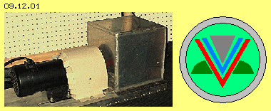 Many details are described at different websites. Nevertheless, everything about that Tilley-story still remains uncertain. Beforehand however one should give credit to any inventor, that he had detected an effect and at this case, he even was able to build suitable machines. As a rule however, remaining problems were not examined or even not noted (and I also know that ´self-deceive´ only too well). As long as one does not know the real cause of the decisive effect, as a rule no optimising is achieved. This is especially valid at these ´immaterial and mysterious phenomena´ of electricity. As long as an inventor can not show a perfect system, nobody believes. These inventors often run into financial problems and a promising idea finally ends at the huge garbage-mass of incapable inventions.
The Tilley-secret is concentrated at a small ´black-box´. Left side of picture 09.12.01 shows a motor (black) and a coupling aside (covered light-grey). A shaft enters the alu-grey cube, with edges about 20 cm long. So inside exists any kind of turning element and thus that box is called ´spinner´. Tow cables reach into the box - and that´s all one knows generally.
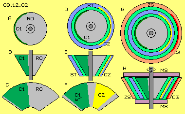 A rotating (truncated) cone shows the property like a flat disc: at increasing longer radius the surface moves increasing faster within space. The elements can be longer stretched at the cone-surface than at the disc-surface. Picture 09.12.02 upside at A shows a view onto the wide side-face of a cone-rotor (RO, grey). A side-view is sketched at B and the outside face is drawn at C.
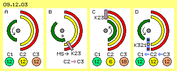 At picture 09.12.03 only these charge-faces schematic are drawn by a cross-sectional view. Each face is some shorter than a half-circle. The charge-face of the rotor (C1, green) is turning around the system axis. The charge-face of the stator (C2, yellow) is stationary and also the charge-face of the intermediate storage (C3, red) is a stationary constructional element. Left side at A, the situation at the start of system is drawn. All faces are charged, e.g. each by 12 V (in comparison with the normal charge of the ground respective earth).
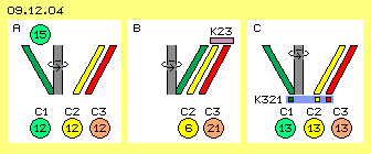 Up to now, that process is a ´null-game´ and the question comes up, how any additional benefit could be achieved. At picture 09.12.04 the positions of the cone-shaped charge-faces are drawn by cross-sectional view. At A the rotor-charge-face (C1, green) is positioned left side and both stationary faces (C2 and C3, yellow and red) are positioned right side. All faces are covered by charges of e.g. 12 V. As discussed at previous chapters, the aether-movements of the rotor-turning add to the aether-swinging of the charges. The charge-face at long radius of truncated rotor-cone is moving faster within space, so there the intensity of charge-swinging is stronger, e.g. representing a voltage of 15 V.
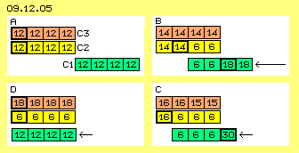 Nevertheless the question remains, how a charge of 12 V (or even 15 V) could pile up a voltage of 21 V. At picture 09.12.05 this aspect is explained by an example of theoretic numbers. All three faces are divided into four sections. At the beginning, all sections are charged by 12 V. At A the rotor charge-face (C1, green) is positioned right side of the stationary charge-faces (C2 and C3, yellow and red).
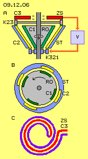 At picture 09.12.06 this conception is sketched once more, upside at A by longitudinal- and below at B by cross-sectional view. As symmetrical shapes are advantageous, at least two charge-faces should be installed at the rotor and at the stator, here for example each four faces are drawn (C1 and C2, green and yellow). The air-gap between C1 and C2 should be some smaller below at the short radius, so upside at the long radius the charge is pressed from the stator to the intermediate storage.
Picture 09.12.07 shows previous constructional elements and basic functions schematic. Based on previous considerations, the ´Tilley-Blackbox´ contains a cone-shaped rotor (RO, grey). For holding the rotor-charge, nearby half of its outward-showing face is build by conductive material (C1, green), divided into several sections, however connected at the narrow end. The rotor is enclosed by a stator (ST, dark-blue) with similar charge-faces (C2, yellow), however some smaller. The stator-faces should be connected by a ring at both ends. An intermediate storage (ZS, dark-red) can be build by different variations. Its charge-face (C3) should correspond to the stator-faces (or could also have variable capacity).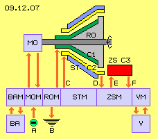 The motor could drive constant or variable revolutions. According to the number of charge-sections results the frequency of generated current-impulses. For example, five sections and 1200 rpm produce hundred impulses each second. This simple rotor could even drive 24000 rpm and produce pulsating current by frequency of 2000 Hz. Even only few charge-volume is moved at each single phase, the performance as a whole will achieve quite usable size. At discussions about such machines, commonly one talks about COP 3 (coefficient of performance) and also Tilley mentioned that number. So one third of the generated performance is demanded for driving the system. As here no electromagnetic processes are used, no back-holding forces come up. Only the much weaker ´Coulomb-forces´ are working against the shifting of charges.
Tilley used eight or twelve 12-V-batteries for supply of components with 72 V to 144 V DC or AC. The system takes the current from batteries (BA) and feeds back the surplus of generated current into that storage. So suitable units for the battery-management (BAM) are demanded. For easier starting and testing the system, naturally other external current-sources (A) could be used. For controlling the motor a corresponding motor-management (MOM) must be installed.
This machine is based on a most simple principle - nevertheless demanding diverse controlling functions. Generally, that ´spinner´ contains only this rotor and its corresponding stator and any kind of intermediate storage - and Carl Tilley said one could buy the material for $ 25 at any craft-shop. These are relative simple constructional elements, nevertheless must be produced mechanically exact, especially for driving high revolutions. For me it was important to offer a logic convincing explanation for that ´blackbox´ - naturally by restriction of liability. Naturally my assumptions and considerations might be false - up to now however one can not find a better variation, at least at the web. One can build that system step by step, beginning with the emergency-switch and on own risk. It will soon become evident, whether and how much charge-back-flow comes up.
09.13. Capacitor-Mystery
09. Aether-Electro-Technics