 Flying is fascinating and today, practically everyone can afford that age-old dream of mankind. Even when airplanes did fly reliable, still some physicists reasoned that machines heavier than air could never fly. Really phenomenal however is, still no theory is commonly accepted. The question why airplanes fly is discussed on and on.
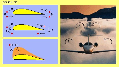
Everyone spontaneous answers this question: ībecause the distance upside of the wing is longer, the air upside moves faster ...ī - like sketched at picture 05.04.01 from A to B. However likely long is also the distance from B to A - and wings installed back to front wonīt fly. At the other hand, any waver-thin sail (with practically same length at both sides) produces a drive force most reliable.
Essentially more professional seams (commonly preferred) Circulation Theory: the air moves around the wing, at the rear end (C) down, downside ahead, at the front side (D) upwards and upside back again. However, continuously air masses can not circulate that kind. The air flows upward at the front of the nose and the air is moving down behind the rear end of the wing - however at the below side, by guarantee, the air will never flow forward, back to the nose.
This theory is based on inevitably coming up vortices behind the aircraft, like clear to see at E and F. These vortices start at the outer end of the wings and reach far back. Itīs assumed all vortex-threats must be closed loop, so these vortices would have to rotate around the wing, from its outer end to the body, and analogue at the other wing, so building a long stretched vortex ring. However, vortex threats not at all must be closed loops. That theory mixes up a (most hindering, secondary) side-effect with the primary cause of the lift-effect.
 Contrary to Formula and Laws
All common theories can not really explain the phenomenon why most strong lifting forces (G) exactly affect where the particles (H) hit most strong at the wing, so should it press down most, thus affecting a force by just opposite vectors. The central point - most not spoken about - however is, that lifting costs nearly null energy input. The airplanes demand energy for drive i.e. to compensate resistance versus the motion ahead. The lifting of the weight versus the gravity however costs minimum or null energy (totally contrary to common understanding of the scientific law of energy constant).
Old Archimedes detected the law of lift and also his ships did swim īfor nothingī at the waters, however only if lighter than the medium. Old Newton with his law of action and reaction is asked for explanations - however it wonīt work as the air shows no mechanical beams. Laws and formula of many known physicists are mentioned, each describing a part aspects of flux-science rather sufficiently - however the lift exists not based on formula, but is based on real movements of real particles. So the cause and the essence of lift are only to detect by description of real processes.
Air Movement
 This animation shows the motion of air particles. At the beginning, they are positioned vertical at that blue line. The picture 05.04.03 shows three situations from that animation.
Already before the wing arrives, the air is īsuckedī towards the nose, even from below areas (A). The particles fly fast along the upper side (B). At the rear end of the wing however, the particles do not meet with their previous neighbours, but the upside particles did fly much longer way into the areas behind (D).
The particles at the below side of the wing, at first are accelerated backward (A). Afterward, the particles stick at a small border layer at the wing and are dragged some ahead (C). At the rear end, the particles again are sucked backward (E). So no clear vortices are coming up (apart from the vortices at the outer ends of the wing) and not at all comes up any circulation.
At the following, the process of lift at wings is described in details. The wing moving through resting air represents some kind of īdisturbanceī, affecting consequences and side-effects. These are important for any application with wing-like elements (e.g. pumps and turbines). So step by step now the causes and affects of lift are discussed.
Trigger Element
At picture 05.04.04 schematic shows a cross-sectional view of a wing (yellow). At first is interesting rear upside part, which in principle is a triangle (A-B-C). The height of that triangle is assumed 0.3 m (H = 0.3) and the length is assumed 1.8 m (L = 1.8). So the relation of length and height is 6:1. When the wing flies towards left that length (B-C), the air particles can fall down that height difference. Thatīs the trigger for all following processes.
The other numbers here are assumed rough for simple calculations. For example, at D the īaction-radiusī (red circle) of a particle (red central spot) is sketched (resp. its maximum way while one second). The molecular speed of that particle is some 450 m/s (VM = 450). The particles however wonīt fly straight ahead all times, but in average they meet diagonal, e.g. when transporting sound. So here at first, the motions ahead are assumed walking zigzag lines and the possibility for moving forward is assumed by sound speed of some 300 m/s (VS = 300). The height H of 0.3 m thus takes one millisecond (TH = 1 MS).
The speed of the plane respective the wing into longitudinal direction is assumed the half of sound speed, thus some 150 m/s (VL = 150). So flying that length of 1.8 m will take 12 milliseconds (TL = 12 MS).
Thin-out vertical
 Upside of the apex of the wing, six particles (red points) are marked representing all air particles (between A and E). When the wing has moved 12 milliseconds towards left side, these particles have more space (from C to F). They can forge down by the distance of height H. Upside of A, collisions occur by normal distances (ND), however upside of C these distances between collisions become longer (LD).
Upside of that part of the wing thus comes up an area of less density. A likely amount of particles within a wider volume, same time stands for less pressure. Instead of īnormalī atmospheric pressure of e.g. 1000 millibar (NP = 1000) thus there exists less pressure, theoretic a īdepressionī of only 917 millibar (TP = 917).
At an earlier chapter 05.02. īThree Times Suction-Effectī this process is described at picture 05.02.02, there by motions of horizontal direction into relative emptiness (while here the analogue process runs into vertical direction). In principle, a first particle falls into the void (as here the wing-face makes the way free for a downward motion) and comes back delayed for collision with next particle. After each two īstrokesī one next particle follows, so the īsuction-areaī spreads upward.
Upward and downward movements not only occur into vertical direction but by zigzag, so with sound speed. After each two movements that īinformationī (more void) moves upward, i.e. by half of sound speed that thin-out of density resp. reduced pressure spreads upward (VP = 150). As here also flight-speed (VL) is assumed by half sound speed resp. these 150 m/s, border of thin-out wanders diagonal backward-upward. That area of less density here is marked red.
Horizontal Wind
Within that area of relative emptiness occur movements not only in vertical direction by longer distances between collisions, but naturally also into horizontal direction the movements occur similar, like schematic sketched at picture 05.04.05.
If a particle at the border of the thinned-out area occasionally is pushed towards right, it also flies a longer distances until next collision (e.g. at G), correspondingly one sixth longer. These particles return with delay to the next collision (e.g. at H), so all locations of collisions (e.g. at I) are shifted correspondingly towards right side.
 A particle positioned at A has the chance for most collisions within the thin area until the rear end of the wing. This particle will finally not be positioned at C (based on its vertical falling) - but same time it will wander to K (based on shifted collisions).
At this snapshot picture, the thin-out starts at A, however the empty area wanders with the airplane towards left side, so a particle momentary positioned at A indeed can fall into that rear end emptiness (which reaches further back behind the plane).
The horizontal movements occur by conditions likely to previous vertical movements. Thatīs why the line F-K shows an angle (to the vertical line) like wing-surface (to the horizontal level). Thus the angle A-C-B is identical to the angle K-F-C. That vertical triangle is one sixth (by H = 0.3) longer, so also the distance C-K is some longer than the height of the wing.
A particle at A wanders towards right side by these 0.35 m during these 12 milliseconds. So the speed of that movement is some 0.03 m each millisecond resp. 30 m/s (VM = 30). Thus based on the īsuction-effectī upside of the slope-part of the wing, a wind of nearby 100 km/h comes up. Even no īnaturalī wind exists at point A (there VW = 0), an īartificialī flow comes up, into contrary direction to the movement of wing, at the rear end showing the strength of a remarkable storm.
At this picture at M is sketched the īaction-radiusī of a īrestingī particle (e.g. far ahead of the wing), which shows the distance of 0.3 length-units until next collision (KD = 0.3, corresponding to the grid-scale used here). At N is sketched the corresponding action-radius of a particle within the area of less density, which is extended towards downside-back (marked as red sickle), because there the distances until next collisions are 0.35 units (KD = 0.35).
That graph is comparable with earlier used īmotion-pattern or -typesī for resting particles and particles within flows of different speeds. Analogue here, a particle within normal environment is marked as motion-type O (after collision positioned anywhere at the round circle). A particle upside-back of the wing is marked as motion-type P (after collision positioned anywhere at that curve reaching one sixth more towards right-side-down).
Real Wind
At the diagonal border line towards the thinned-out area thus the particles will accelerate from 0 to 100 km/h immediately. Thatīs no problem as all particles at frontal collisions īaccelerateī form 0 far above sound-speed (e.g. normal molecular speed of 470 m/s * 3600 s = 1692 km/h). However that wind starts not just at the border line, because any particle flying over the wing leaves a relative void above the front side of the wing. In addition, the horizontal movement naturally results a progressive thin-out at the areas further in front of the wing.
At picture 05.04.06 left side, that secondary thinned-out area is marked dark-red up to a vertical line near the apex of the wing (A). The speed of the wind (VW) is noted for six layers of air. The speed is calculated by simple average of the particles ways before and behind the border line. So resulting are flows increasing faster from upside down by e.g. 3, 7, 12, 18, 24 respective 30 m/s.
 Previous thin-out into vertical direction produces wandering movements, as all particles as a whole are moving some down. However thatīs no real wind, because every particle inevitably is rejected at the face of the wing. None of these particles can leave that local area (these vertical movements can not escape into the wing).
Opposite however, the horizontal movement is a real wind as the particles wander out into areas behind the wing. They are not rejected at a certain point (like previous surface), but will mutually collide finally some later. Some particles probably escape in total from their original location, because far behind still exists a relative void resp. that wind is running further on far behind the wing. One also should remember, not only single particles are moving but real crowds are falling into inevitably existing īempty bubblesī (see earlier chapters).
This horizontal flow-component thus wonīt end upside of the rear end of the wing and that wind does not start at previous border line. The thin-out-effect of that īreal windī spreads forward along the wing and far in front of the nose, not only with half of sound-speed (as the vertical thin-out spreads upwards). That īinformationī (collision partner wandering off rear end) is obvious just for any particle whenever itīs hit occasionally into rear-end direction, i.e. the information of new possible movement wanders ahead by speed of sound.
At this picture right side, the speeds of air layers are show as shifted-motions of particles which previously were positioned straight vertical line upside of the apex of the wing. This graph corresponds to the black line resp. the curve of upside animation resp. at picture 05.04.03. From upside down the wind becomes faster and the particles wander off rear end of wing (which same time moves towards left side), at below layers much faster and wider than at layers further upside.
Suction of fast Flow
Between neighbouring flows of different speed exists a suction-effect, described in details at earlier chapter 05.02. īThree Times Suction-Effectsī. Between involved movement-types (e.g. also concerning the īaction-radiusī respective type P at previous picture 05.04.05) occur īrear-end-collisionsī. At the one hand each faster flow is compressed (and/or becomes bended). At the other hand the particles occasionally fall into the faster flow without resistance, and thus they affect an increasing density and speed of the faster flow. At this process are involved not only single particles, but based on the void and uneven spreading of particles within gases in general, whole crowds or parcels fall into fast driving bubbles.
This effect occurs everywhere within the whole volume of these flows, thus also within that areas upside of the wing at all locations. Previous calculations concerning pressure and speed might theoretical be right, however can never mirror real the processes exactly. By known and most effective īsuction effect of faster flowsī (see hurricanes etc.) the flux alongside a surface becomes much faster and also the spreading of density is much more distinct.
Vortex-Train
At the rear end of the wing thus exists a storm-like flow backward-down. This flow meets the air from below the wing, which is īrestingī resp. some turbulent because sticking at the surface. The flow from upside hits onto downside air masses and compression comes up. This process occurs on both sides of airplane body, so the increased pressure can expand only outward-aside.
Opposite, this downward-movement still īdragsī air from upside down, same time previous thin-out spreads further upside. So an inflow of air can come only from relative resting areas aside of the plane. In addition all these flows are moving backward off. Resulting are these double vortices cylinder, like shown most impressive at previous picture 05.04.01 at E and F.
Also these vortices border on neighbouring areas of slower movements, so also far behind the plane that suction effect of each faster flow is working. These both vortices trains build contrary turning tornados inclusive their self-acceleration. Large planes mix up the air space for minutes. However, that occurrence is secondary side-effect, a most hindering appearance. Certainly, itīs not at all the primary reason for the lift at wings (as some theories assume).
The lift really is affecting at that rear part of the wing. Downside of the wing, nearly normal atmospheric pressure exists. Upside of the wing, that wind glides alongside the surface diagonal down. The windīs static pressure is much less and the pressure difference affects as an upward directed force. Nevertheless, the prevailing part of lift-forces appear at the front side part of the wing, so the processes there must be considered.
Information ahead
 At picture 05.04.07 again the yellow wing is drawn and the primary (vertical) thin-out area upside-back is marked light-red. The profile of the wing at its rear part (in principle) is triangle-shaped and takes nearby three quarter (B-C) of the total length of the wing. The secondary (horizontal) thin-out area again is marked dark-red, now however drawn also further ahead.
Upside correctly was assumed the spreading of that thin-out (resp. upside in the figurative sense was also called īinformationī) into horizontal direction occurs by sound speed. Valid as a clear approval is the fact, the lift at wings disappears if the plane flies ultrasound-speed. Each wing-profile shows a special characteristic graph concerning the relation of speed and lift. Increased speed results increasing lift force. However, each excessive speeds reduces the lift and finally it disappears in total.
Starting point of these considerations was, the primary trigger for that lift-force occurs at the apex of the wing (B) and the effect is completely build out at the rear-end of the wing. At previous example was assumed, the plane is flying by half sound speed. As previous īinformationī is running by sound-speed within space, itīs running ahead of the moving plane (with its half-sound speed), also by half sound-speed. Here now at this picture is assumed, that information becomes affecting at least three of these quarters ahead of primary trigger-point B.
Right side are drawn again these lines of previous picture 05.04.06. They represent the shift of neighbouring particles by these winds of different speed. New curves right side are adjusted as differences to the vertical direction. However one must consider, stronger winds represent stronger īsuctionī (by shifting of their locations of collisions) and thus show stronger effects concerning particle further ahead. The higher ordered and faster the flow, the less negative collisions occur and the less resistance exists for following particles.
Suction by Void and fast Flow
The thinned-out space and speed of winds thus reach ahead not linear but the intensive movements affect correspondingly stronger into the space in front of the wing. Maximum speed exists alongside the wing upper surface, so its īsuctionī reaches also ahead of the nose towards downside-ahead. These winds still wonīt drag any particles, but they only offer a void space for particles which occasionally were hit into likely directions - here even from below-ahead just over that nose.
 At picture 05.04.08 again are drawn these īvertical wind-curvesī, now in addition accentuated by īhorizontal curvesī of different air layers. Depending on the wind speeds, these partial areas are coloured, from resting air (dark blue) to most fast flow (light blue).
Like at flows of different speed at the rear part of the wing, strong flows alongside the front part of the wing were affecting strong īsuctionī to neighbouring flows. In addition, the surface there is bended and alongside curved surfaces that suction-effect is most effective.
Flow-threats are bended towards faster flow all times and also that flow by itself becomes bended - and now can fly that curve without resistance (like described in details at chapter 05.02 īSuctionī at picture 05.02.05). By view from below of the nose, the surface steady turns aside and thus additional void appears with corresponding suction. The curvature of profile at this part is critical concerning the lift and the resistance. It must be adapted to the flight-speed wanted.
Order Factor Wall
Repeatedly I pointed out the function of walls at the characteristic of flows. The sloped end of the wing represents a relative void and was described as the trigger for the vertical thin-out. A corresponding wall does not exist for the horizontal movements, so a real wind comes up with shifting particles backward far off.
Within free space all local areas of relative void can be filled up from all sides. As described in details by basic chapter 05.02. at picture 05.02.05, the void aside of a wall however can only be filled up from outside and prevailingly alongside the wall. Thatīs valid here along the total upper face: behind the apex appears relative void, which spreads to the front side parts as strong winds. Any fast running particle appears like void for any following particle - and just that void never is filled up from the wall, thus exists continuously.
Minimum and maximum static Pressure
As ahead and above of the nose that īsuctionī can only be filled up from downside, and as the bended flow there can flow without resistance around the curved face, just at this part of wingīs upper surface exists maximum speed. Not only direct at the surface but also each upper layer of air shows its maximum flow just there. At these parts of light colours frontside-upward, thus within all layers exists minimum pressure cross to the flow directions. So there at the wing surface weights most less static pressure. The air indeed escapes upward in front of the nose, so the wing flies forward all times into an area of most less pressure - with relative few resistance.
Onto the below surface of the wing, in principle weights the total atmospheric pressure. However, the air of that region is not totally calm but is sucked back little bit, afterwards itīs dragged some ahead, finally sucked backward at the rear end. So also at the below surface affects the atmospheric pressure not by total strength. The difference of static pressures between upside and downside surfaces results the wanted lifting force.
Rough Calculation of Lift-Forces
Many formula are used for calculating these forces. The mentioned circulation-theory for example works with a factor īcirculationī (deduced of backside vortices trails resp. representing practically speed differences between upside and downside surfaces of wing). Other calculations assume, the lift-forces should correspond to the air masses pushed down (so a pure mechanical view without any consideration concerning suction effects). Mostly are used Cw- and Ca-numbers (which however are determined empirical for every profile and angle of attack). Mostly is used the density of the medium (while pressure probably would be the factor more realistic). The factor of speed, all times is used by square (probably too simplistic view). Only the scale of the effective face is a clear factor at common calculations of lift-forces.
All common formula however do not fit to the fact, above sound-speed no lift is achieved (thus the factor sound-speed theoretically should be involved at any formula). So I offer an attempt for calculations, deduced from the real reasons of the processes producing the lift-force (using the data of pictures 05.04.04 and 05.04.05).
Behind apex (A) of the profile, the air can fall down at the distance H during the time TL (until the wing moved the distance L towards left). The horizontal wind corresponds to previous downward-speed plus an additional part corresponding to the relation H / L (previous one sixth), so the wind of this example achieves 30 m/s within the space.
This wind continuously fills up (by parts) the void alongside distance L. Based on suction, corresponding mass of air must come from front side, however alongside the shorter distance from the apex to the nose. The front part of the profile here was assumed one third of rear part, so in front of the apex the wind should move three times faster, for example thus by 90 m/s i.e. some 300 km/h. The average speed alongside whole upside face thus would be some 45 m/s ((3*30+1*90)/4).
Now the dynamic pressures are calculable (by Bernoulli formula), at the below face of the wing with flight-speed of 150 m/s and at upside face with the flight-speed plus the wind, so of 150 + 45 = 195 m/s. Instead of that relation resp. factor of 195 / 150 = 1.3 commonly the speeds are calculated by square, so the factor 38.025 / 22.500 = 1.7 would result for the dynamic pressures. As the remaining static pressures relate contrary, the factor of some 1 / 1.7 = 0.6 is resulting respective a difference of 0.4 in favour of the upside surface.
The atmospheric pressure weights by one metric ton each square-meter, so the lift-forces of that wing would be 1000 * 0.4 = 400 kg/m^2. The wing was assumed with a length of 2.4 m and a span e.g. of 20 m would result a surface of 48 m^2. So by that rough calculation would result a lift force of 400 * 48 = 19.600 kg - and qualified men are invited to check these data.
Sound-Barrier
At this example roughly was calculated a wind of 90 m/s at the front part of wing. This part is 0.3 m high and 0.6 m long, the flight-speed is 150 m/s, so the air in average already needs 75 m/s to escape upward. Only if these high wind-speed at the nose comes up, these extreme low Cw-values of wing profiles are possible (a rod with a diameter of only 3 cm resp. 7 cm^2 produces more resistance than that wing of 2.40 * 0.3 m resp. some 3.200 cm^2 cross-sectional surface).
If this plane should fly faster, the relation of height and length must be reduced, i.e. profiles more flat must be used. The wind-speed in front of the nose must accelerate already far ahead. The īinformationī of that wind resp. its suction-effect is running through the space by sound speed. Finally when the plane by itself flies with that speed, the wind no longer can escape the nose of wing. Suddenly a ībow-waveī of dense air comes up. The plane must push these masses continuously forward, i.e. must accelerate the air in front. Inevitably come turbulences, no longer exist ordered flows along the surfaces, so the prerequisite for the lift-effect got lost.
New Theory of Lift
At picture 05.04.09 once more are shown previous areas of winds and pressures, now by smooth colour-nuances. The movement processes and effects are marked by arrows. This new theory of lift here is summarized in brief, by different steps from the initiating cause to final the effect.
Preliminary is to state, īsuctionī never works any kind īdragging or attractingī, but suction only offers longer distances until next collision, only for particles which got pushed occasionally into that direction, just by normal molecular movements. Above this, the particles there can fly more narrow aside each other and the flow shows a better structure and better order. The term īsuctionī here is used exclusive by that sense and understanding.
 A. The trigger reason for lift is the sloped upside surface of the rear of the wing, which continuously produces a relative empty space while the plane is moving ahead. Into that void the particles fall down in vertical direction. They are rejected by the surface and return upward with some delay.
B. The region upside of that original void also becomes thinned-out, as the locations of all collisions are shifted some down. The ways between collisions become some longer. The area of reduced density spreads upward by half sound-speed.
C. Into that thinned-out area, the particles fall also in horizontal direction, and also these ways between collisions become longer. These backward showing motions are not limited by certain surface, so a real shift of particles exists. That wind does not stop at the rear end of the wing, but is steady flowing off, also behind the plane. As that thinning-out spreads from below upward, the wind near the surface can start earlier and becomes stronger than within air layers further upside.
D. At neighbouring flows of different speeds, each faster flow affects like a suction towards neighbour flows. The particles of the slower flow are integrated within the faster flow without resistance. The fast flows within below layers become more dense and accelerated.
E. These winds wandering over the wing backward, represent also suction for areas ahead. They leave relative void at the front. That void spreads above and ahead of the wing by full sound-speed. That void alongside the surface can only be filled up from upside and prevailingly along the face from areas ahead. Winds even exist far upside of the wing, however the motions along the surface are most strong.
F. The most strong flow at the front part of the upper surface affects correspondingly strong suction effect. Even the particles below of the nose-level are īdrawnī up over the wing.
G. Areas far ahead show slow motions at the beginning. When they come to the nose, they affect bending, compressing and accelerating the fast flow near the face. As the face upside and behind the nose is curved, the bended flow can run without resistance.
H. Downside of the wing, the air keeps not totally calm, nevertheless is affecting nearby the whole atmospheric pressure onto the below surface of the wing.
I. At the upside surface the static pressure is reduced corresponding to the speed of that wind alongside the face. The difference of static pressures of upside and downside surfaces represents the lifting force, which in total shows vertical upward and some ahead. The īproductionī of that lift costs no corresponding energy-input, because the īprotectionī of the upside surface versus the atmospheric pressure exclusively is based on suction, the wind there comes up automatic, as particles fall into each relative emptiness by pure chance and based only at normal molecular motions.
The readers may judge whether my new theory of lift is a logic and understandable description of the real cause, the processes and effects of that īphenomenonī - and the readers may well compare these statements with other theories. Next chapter 05.12. īA380 and Liftī will show an approval by calculations of realistic data.
File www.evert.de/ap0504e.pdf is a print version.
| 05.12. A380 and Lift | Aero-Technology |